- Home
- Technology
- Ricoh's Technology
- Visualizing Paper Feed behavior in Fusing Unit
Main content
Main content
Visualizing Paper Feed behavior in Fusing Unit
This technology makes it possible to visualize paper behavior fed inside a printer, thereby enabling numerical quantification. It achieves reliable machine design against paper wrinkles.
Significance of visualizing mechanism of paper wrinkle problem
Copiers and printers based on the electrophotographic system make prints by fixing paper with toner using heat and pressure. In this fixing process, stable paper feed must be controlled to maintain typography of the prints. This is needed because, if paper feed at the fusing unit becomes unstable, paper wrinkle may result.
In developing a new fusing unit in the past, we confirmed whether or not stabilized paper feed could be achieved by conducting repeated paper feed tests under varied conditions and environments. That method allowed us to evaluate whether or not paper wrinkle occurred. It did not, however, clearly illustrate which components in the paper feed had the greatest influence on the unstable behavior that resulted in paper wrinkles.
As a remedy, Ricoh developed a "paper feed behavior visualization technology" to clarify the mechanism in which paper wrinkle occurs. We then measured how much influence the difference in paper variety or component shape constituting the fusing unit imparts on paper behavior, and clarified the quantitative relationship. If we know "the degree of paper behavior change depending on the degree of change in composition of each component," and "the degree of permissible instability against paper wrinkles with a certain paper behavior," a reliable fusing unit can be designed.
Visualization example in velocity distribution
One paper behavior affecting wrinkle generation is "velocity distribution" of the paper being fed. A wrinkle occurs when the central part of a sheet advances faster than the edge. On the other hand, it does not occur when the edge of a sheet advances faster than the central part. The velocity distribution of paper is determined by the shape of the fusing unit components.
Figure 1 shows an example of velocity distribution generated on a sheet of paper. When velocity distribution becomes as shown in the figure, the force to move to the inner side will be applied to the paper that passes through the fusing unit, and heave-up deformation will easily occur.
Figure 1 shows an example of velocity distribution generated on a sheet of paper. When velocity distribution becomes as shown in the figure, the force to move to the inner side will be applied to the paper that passes through the fusing unit, and heave-up deformation will easily occur.
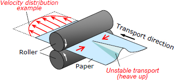
Fig. 1: Schematic diagram of paper behavior being transported inside the device
(Where speed is faster at the central part than at the paper edge)
Figure 2 shows the size of heave slope inclination in different colors, measuring the geometry of the heave generated on the paper. Multiple heaves have generated near the center of the paper. If the paper passes through the fusing unit in this greatly deformed state, paper wrinkles will occur.
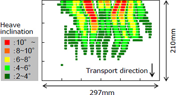
Fig. 2: A heave example in paper generated after unstable transport.
(Heave slope inclination shown in different colors)
To prevent paper wrinkles, the paper needs to be transported at a velocity distribution that keeps deformation small. Further, a composition of components that allows transportation in such a velocity distribution is needed. When we understand the quantitative relationship among "the component shapes," "the velocity distribution of paper" and "the deformed shape of paper," including the influence of the paper variety and the environment, we are able to design a component formation that allows stable paper transport.
Achieving efficient design of reliable fusing unit
The development of visualization technology has revealed the paper wrinkle problem in a fusing unit; until now, the origination mechanism was ambiguous. Further, we found that evaluating the paper transport velocity distribution and the deformed shapes to be effective as alternative indices for handling paper wrinkles quantitatively. Using these indices, we are able to opt for a fusing-unit component formation free from paper wrinkles.
Although this technology’s purpose is to visualize the phenomena that actually happen, it can be applied also to evaluate the design by simulation. The technology is also used in designing printer fusing units that use the electrophotography system. This results in faster time to market of new models. Beyond that, it yields designs with a high margin against the paper wrinkles, thereby ensuring printers of high reliability.
Although this technology’s purpose is to visualize the phenomena that actually happen, it can be applied also to evaluate the design by simulation. The technology is also used in designing printer fusing units that use the electrophotography system. This results in faster time to market of new models. Beyond that, it yields designs with a high margin against the paper wrinkles, thereby ensuring printers of high reliability.
Sorted by : field “Electrophotographic” “Analysis / Simulation” | product type “Analysis / Simulation”